T&C LAB-AI
Dept. of Intelligent Robot Eng. MU
Robotics
Mobile Robot
Kinematics
Lecture 3
Jeong-Yean Yang
2020/10/22
1
T&C LAB-AI
Mobile Robot Kinematics
1
2
T&C LAB-AI
Dept. of Intelligent Robot Eng. MU
Robotics
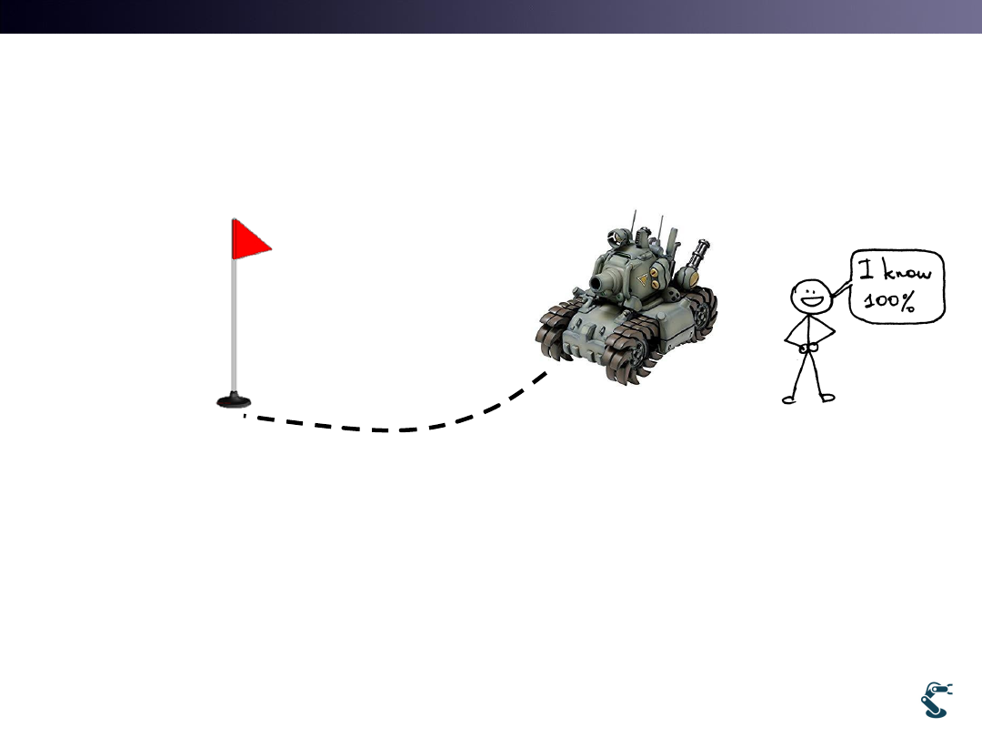
How to Drive a Mobile Robot?
• Mobile Robot is very familiar with Everybody.
– We have played Plamodel Tank or Game.
• But, in Robotics, we know PD or PID Control.
– What will be the Desired Angle for approaching the goal?
– It is tough…
3
Goal
T&C LAB-AI
Dept. of Intelligent Robot Eng. MU
Robotics
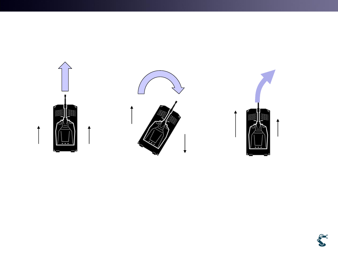
Control in Mobile Robots
• Control with Joystick is Easy Visual Feedback
• Control with CPU for Moving No Feedback
– It means that we must know Complex Kinematics
4
Left
Right
Left
Right
Left
Right
T&C LAB-AI
Dept. of Intelligent Robot Eng. MU
Robotics
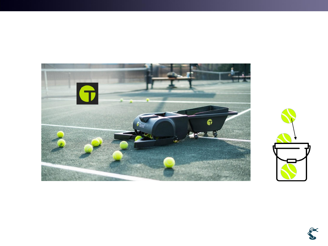
Problems of Tennibot
5
Tennibot
• Ball Detection Ball Position Robot Moves
– How tennibot moves?
• Where is a Bucket after collecting balls?
T&C LAB-AI
Dept. of Intelligent Robot Eng. MU
Robotics
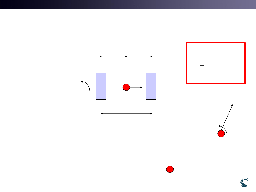
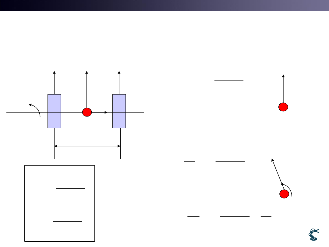
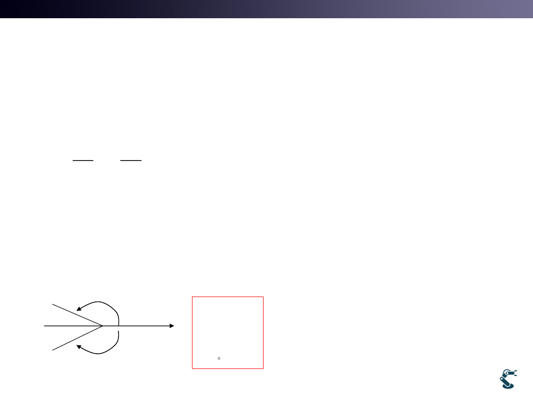
Differential Drive Kinematics
6
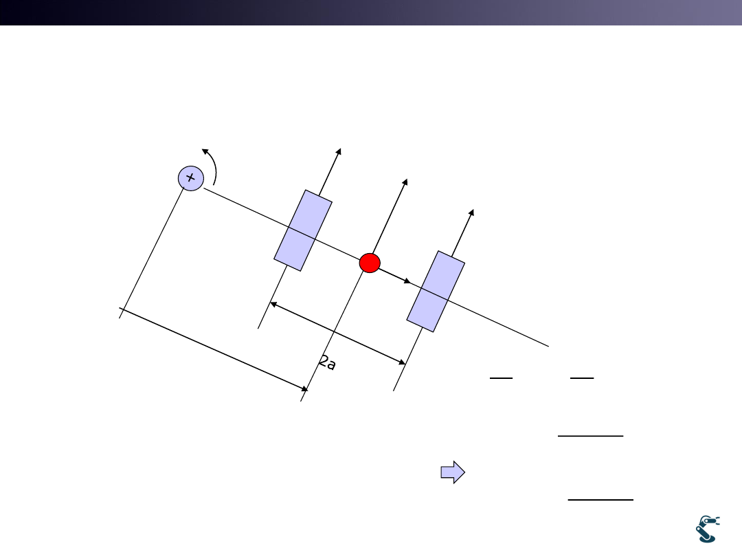
2a
L
v
R
v
+
w
w: Angular velocity
vL: left velocity
vR: Right velocity
Question: Velocity of Red mark ?
when vL, vR is given.
+
w
v
2
L
R
v
v
v

T&C LAB-AI
Dept. of Intelligent Robot Eng. MU
Robotics
7
L
v
R
v
+
w
v
T&C LAB-AI
Dept. of Intelligent Robot Eng. MU
Robotics
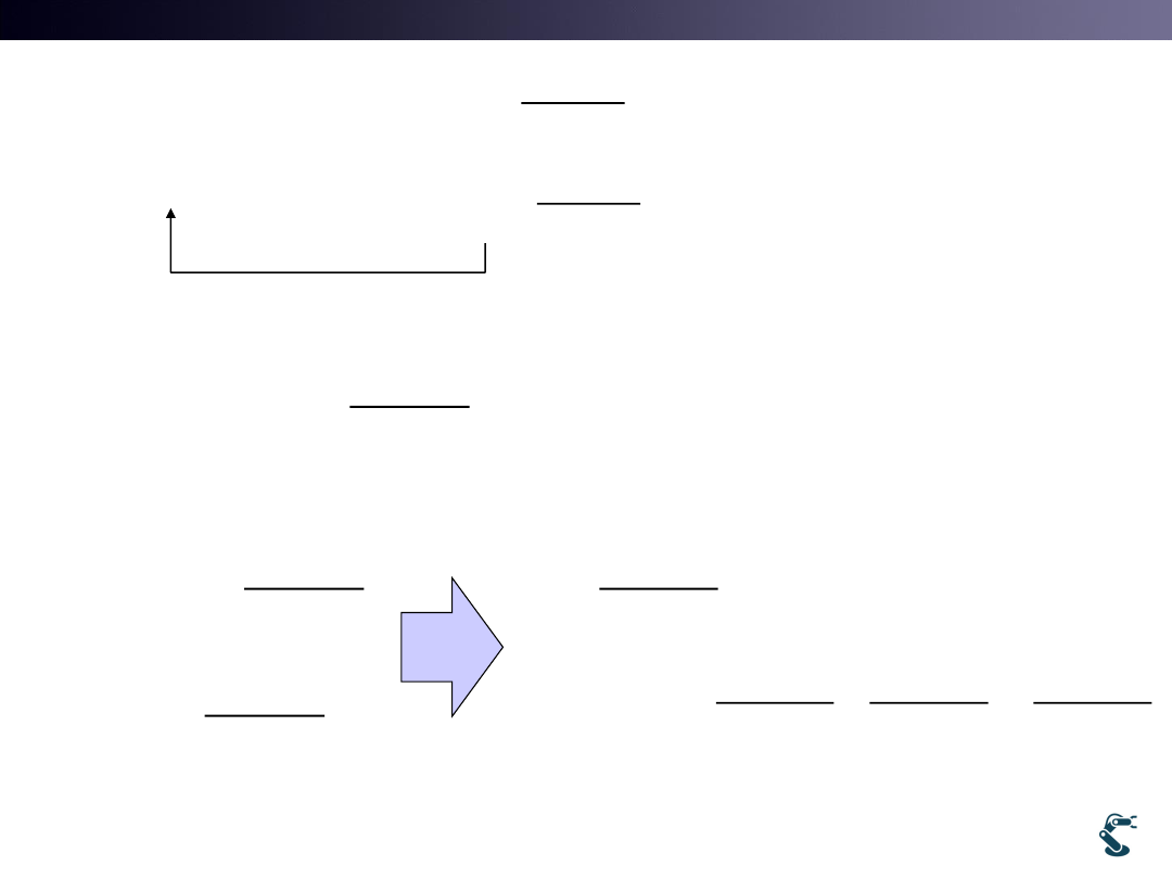
Differential Drive Kinematics
8
L
v
R
v
w
ICC
ICC: Instantaneous
Center of curvature
R
(
)
(
)
L
R
v
w R
a
v
w R
a
L
R
v
v
a
a
R
w
w
2
2
R
L
R
L
v
v
a
w
v
v
w
a
Remind that
v
w r
T&C LAB-AI
Dept. of Intelligent Robot Eng. MU
Robotics
9
L
v
R
v
+
w
v
2
R
L
v
v
w
a
2
L
R
v
v
v
T&C LAB-AI
Dept. of Intelligent Robot Eng. MU
Robotics
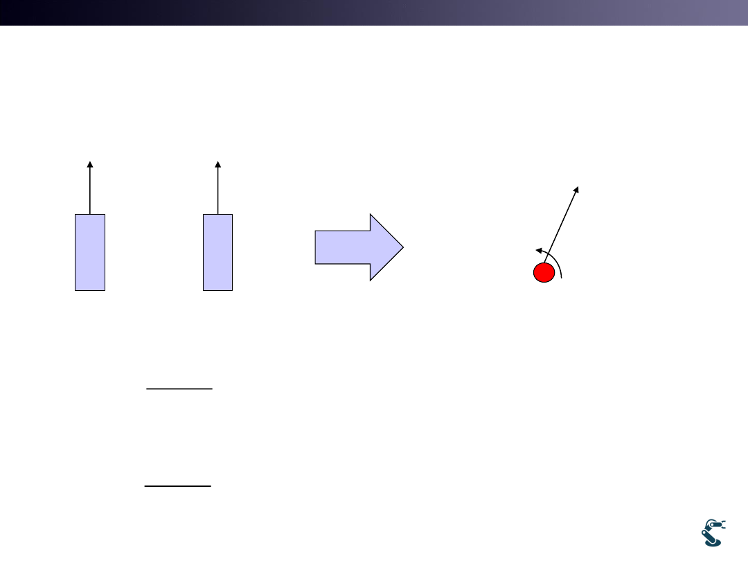
Differential Drive Kinematics
10
2a
L
v
R
v
+
w
+
v
2
R
L
v
v
w
a
1)
0
2
R
L
R
L
v
v
case
w
a
v
v
v
+
w
v
Linear motion
2)
,
0
2
L
R
R
R
L
case
v
v
v
v
v
w
v
a
3)
0
,
2
2
2
L
R
R
L
R
case
v
v
v
v
v
w
v
a
2
L
R
v
v
v
T&C LAB-AI
Dept. of Intelligent Robot Eng. MU
Robotics
11
(
)
(
)
L
R
v
w R
a
v
w R
a
2
2
R
L
R
L
v
v
a
w
v
v
w
a
(
)
(
)
2
2
(
)(
)
2
R
L
L
L
R
L
L
R
L
R
L
R
L
v
v
v
w R
a
R
a
a
av
v
v
R
a
av
R
a
v
v
v
v
a
v
v
2
(
)
2
2
L
R
R
L
R
L
L
R
R
L
v
v
v
v
v
v
v
v
v
wR
a
a
v
v

T&C LAB-AI
Dept. of Intelligent Robot Eng. MU
Robotics
Differential Drive Kinematics
12
1
1
1
1
2
2
2
2
1
1
1
1
2
2
2
2
L
L
R
R
v
w
v
r
v
w
w
a
a
a
a
1
1
L
R
a
w
v
r
r
w
a
w
r
r
T&C LAB-AI
Dept. of Intelligent Robot Eng. MU
Robotics
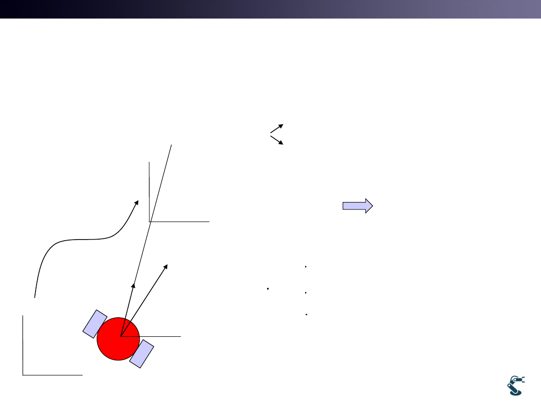
Kinematic Position
13
v
x
y
X
Y
cos
sin
x
y
v
v
v
v
x
X
y
v
cos
cos
0
sin
sin
0
0
1
x
v
v
X
y
v
w
w
g
g
g
g
x
X
y
goal

T&C LAB-AI
Dept. of Intelligent Robot Eng. MU
Robotics
Jacobian Matrix
14
cos
cos
0
cos
0
2
sin
sin
0
sin
0
0
1
0
1
2
1
1
cos
0
cos
cos
1
2
2
sin
0
sin
sin
1
1
2
0
1
1
1
2
2
L
R
R
L
L
R
v
v
x
v
v
X
y
v
v
v
w
w
a
v
v
a
a
a
a
cos
cos
cos
cos
1
sin
sin
sin
sin
2
2
1
1
1
1
L
R
L
L
R
R
v
v
rw
w
r
rw
w
a
a
a
a
r: wheel radius

T&C LAB-AI
Dept. of Intelligent Robot Eng. MU
Robotics
Jacobian for Cartesian Control
• Our goal is from x,y,q xd,yd,qd
• Inverse of Jacobian matrix is required.
• But, J = [ 3x2]… how to find inverse matrix?
15
cos
cos
sin
sin
2
1 /
1 /
L
R
x
w
r
X
y
w
a
a
r: wheel radius
wL : left wheel angular velocity
wR : right wheel angular velocity
( , , )
x y
𝑥𝑑, 𝑦𝑑, 𝜃𝑑
T&C LAB-AI
Dept. of Intelligent Robot Eng. MU
Robotics
Kinematic Position
• Remind that x, y are defined at general coordinate
• But, in many cases localization is difficult.
* Localization: knowing where it is.
• New transform is required. Polar coordinate
16
cos
cos
sin
sin
2
1 /
1 /
L
L
R
R
d
d
r
dX
J
Jd
d
d
a
a
cos
cos
sin
sin
2
1 /
1 /
L
R
x
w
r
X
y
w
a
a
T&C LAB-AI
Dept. of Intelligent Robot Eng. MU
Robotics
17
v
x
y
X
Y
2
2
2
2
(
)
(
)
tan 2(
,
)
tan 2(
,
)
X
x
Y
y
x
y
a
y
x
a
y
x
cos
sin
sin
v
v
w
v
w
cos
0
sin
1
sin
0
v
w
Polar Coordinate
T&C LAB-AI
Dept. of Intelligent Robot Eng. MU
Robotics
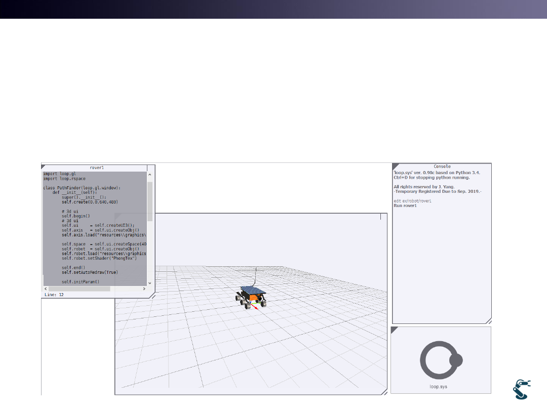
Simulation Environment
• 3D Mobile robot in graphics
• Python Script for control objects
18
3D Graphics
Python
Console
Python
Script
T&C LAB-AI
Dept. of Intelligent Robot Eng. MU
Robotics
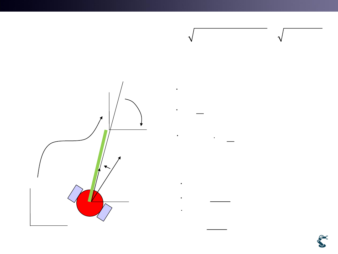
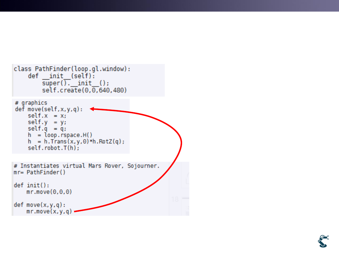
Ex) rover1.py
Graphical Movement
• “edit ex/robot/rover1”
– Press F5 for Run code
• rover1. move(x,y,q)
• rover1.move(0,0,90)
90 degree rotation
• rover1.move(5,0,-90)
move to (5,0) and -90
degree rotation
19
( , , )
T
R
H x y
H H
New coordinate
direction
T&C LAB-AI
Dept. of Intelligent Robot Eng. MU
Robotics
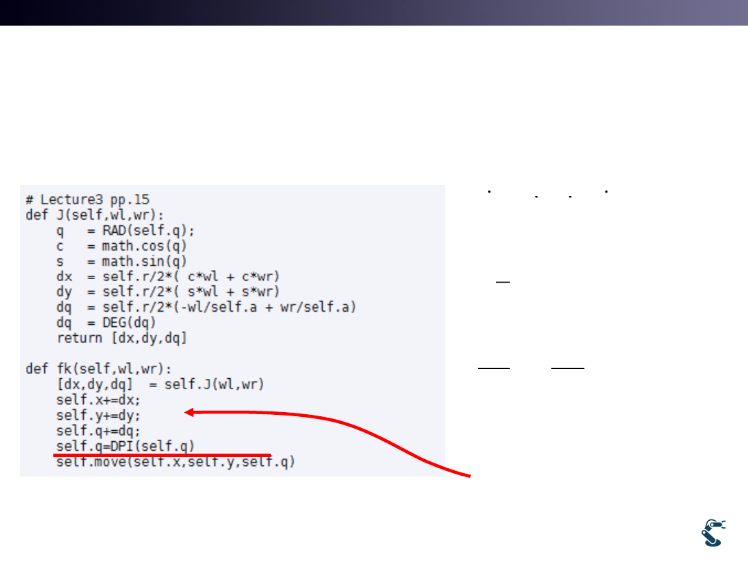
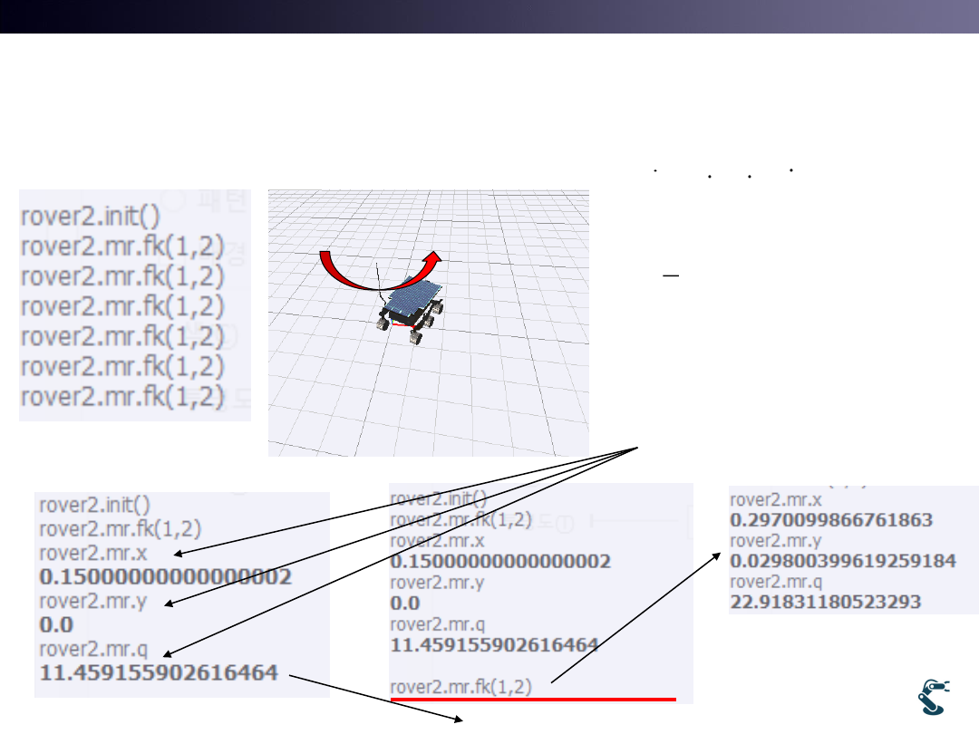
Ex) rover2.py (with Jacobian Matrix)
Forward Kinematics(fk) and J matrix
• Jacobian J at pp.15
• [x,y,q]=FK(wL,wR)
• X’= X+ dx=X+J*dq
20
cos
cos
sin
sin
2
1 /
1 /
T
L
R
X
x
y
w
r
w
a
a
dX
d
J
dt
dt
T&C LAB-AI
Dept. of Intelligent Robot Eng. MU
Robotics
What is DPI function? (Very Important)
• Mobile Robot Kinematics is calculated by Jacobian.
• But it is a Periodic Function
21
3
'
'
rd row
dX
d
J
dt
dt
dX
Jd
X
X
dX
X
Jd
J
d
Ex)
If q is 170 degree,
….
q’=q+30
q’= q+30 = 200 degree
No problems for graphics or SLAM
* Problem occurs for Control
Error of q = qd-q = (-170)-200
= -370
Think T = Kp * (Error of q)
q
qd
170 deg.
-170 deg.
170 170
20
d
e
q
q
or
T&C LAB-AI
Dept. of Intelligent Robot Eng. MU
Robotics
Ex) Forward Kinematics with rover2.py
WL=1 and WR=2
22
cos
cos
sin
sin
2
1 /
1 /
( )
T
L
R
L
R
X
x
y
w
r
w
a
a
w
J
w
X
X
dX
X
Jd
x
y
q
(0)
J
(11.45915)
J
T&C LAB-AI
Dept. of Intelligent Robot Eng. MU
Robotics
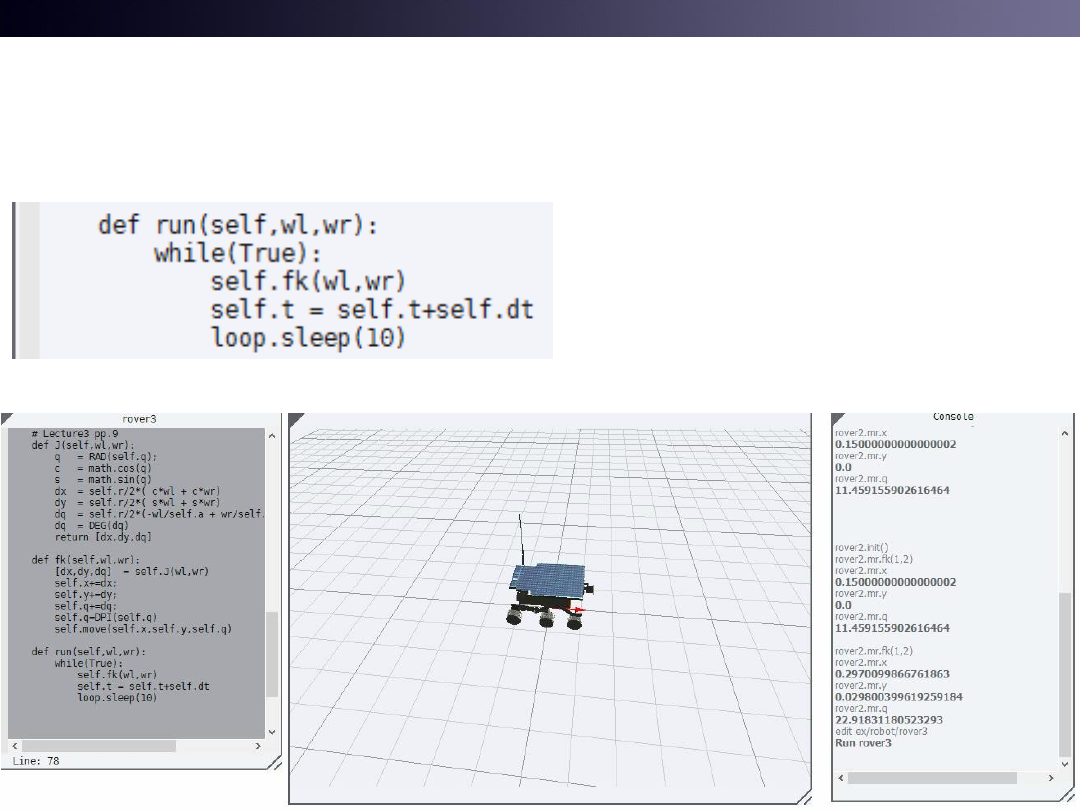
Ex) rover3.py for Control Loop
• run() starts infinite
loop.
• Type “Ctrl+D” on
console for stopping
control loop
23

T&C LAB-AI
Dept. of Intelligent Robot Eng. MU
Robotics
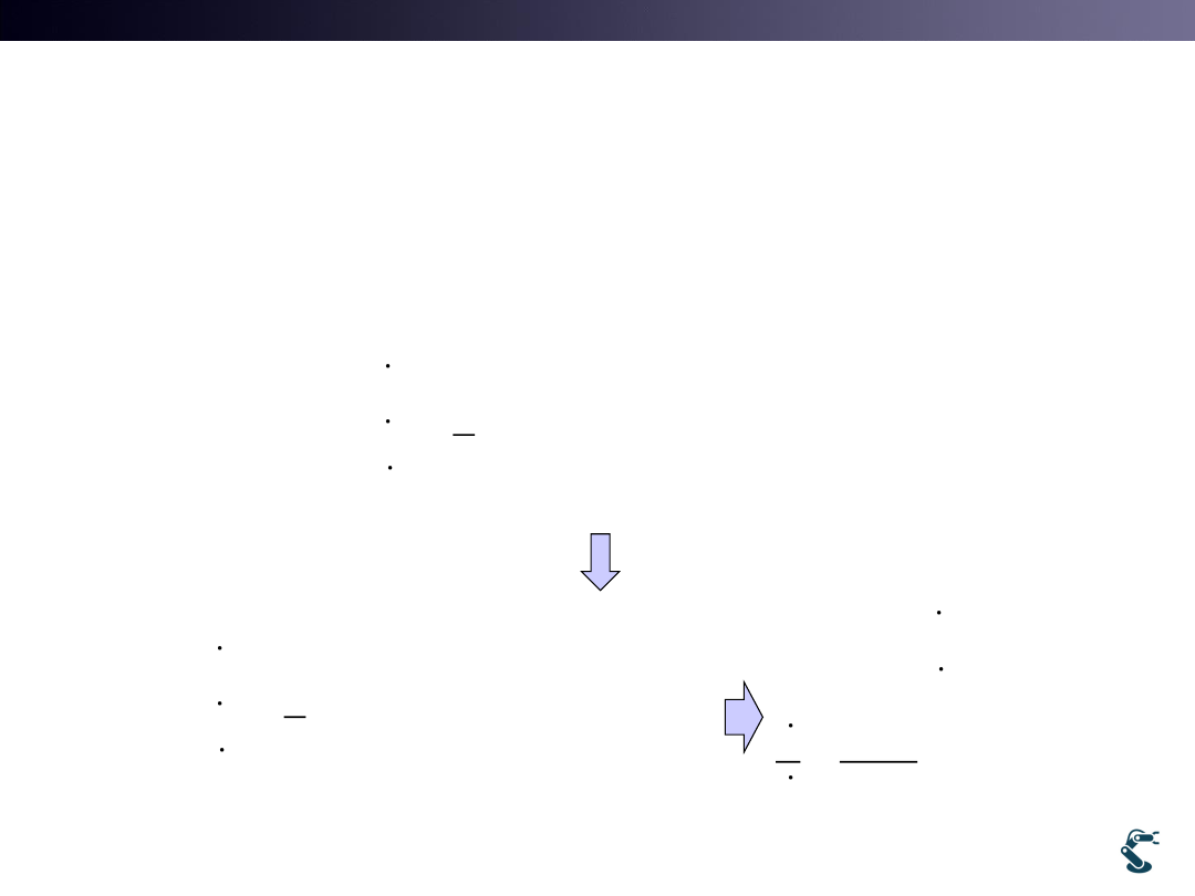
Inverse Kinematics
• Forward Kinematics of Mobile Robot
• Is it Invertible? It is NOT a Rectangular Matrix.
• How we find a Inverse Kinematics?
– We cannot derive IK directly by using inverse matrix.
24
(
,
)
T
T
L
R
X
x
y
w w
dX
Jd
(
,
,
)
(
,
)
'
(
,
)
L
R
L
R
x
y
J
X
X
X
FK
Input: 2
Output: 3
'
(
,
,
)
IK
x
y

T&C LAB-AI
Dept. of Intelligent Robot Eng. MU
Robotics
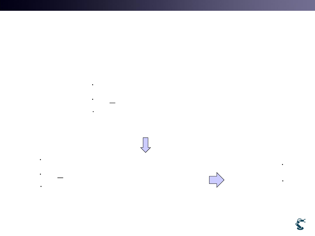
Two Inverse Kinematics Approaches
• 1. Simple Method
– Rotation – Translation – Rotation
• 2. Inverse Kinematics with optimality
– Lack of DOF.
25
T&C LAB-AI
Dept. of Intelligent Robot Eng. MU
Robotics
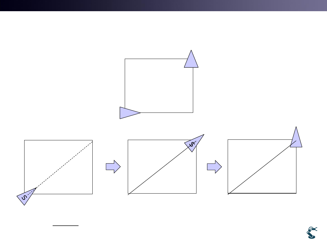
Ex) rover4.py
• Simple Strategy: rotation – translation - rotation
26
S
F
(x,y,q)
(xd,yd,qd)
1
Rotation first
1
1
tan
d
s
d
y
y
x
x
2
Translation
0
(
,
)
d
d
d
X
x
y
with w
S
3
Rotation for qd
d
T&C LAB-AI
Dept. of Intelligent Robot Eng. MU
Robotics
I. Simple Inverse Kinematics Strategy
Case 1) Only Translation
• Assume that WL=WR=Wo
27
cos
cos
sin
sin
2
1 /
1 /
L
R
x
w
r
y
w
a
a
2 cos
r cos
2 sin
r sin
2
0
0
o
o
x
r
y
w
w
0
0
/ ( cos )
/ ( sin )
cos
sin
L
R
w
w
x
r
w
w
y
r
x
y
T&C LAB-AI
Dept. of Intelligent Robot Eng. MU
Robotics
I. Simple Inverse Kinematics Strategy
Case 2) Only Rotation
• Assume that WL= (-)WR WR= wo and WL=(-)wo
28
cos
cos
sin
sin
2
1 /
1 /
L
R
x
w
r
y
w
a
a
cos
cos
0
sin
sin
0
2
1 /
1 /
/
o
o
o
x
w
r
y
w
a
a
rw
a
0
0
/
/
L
R
w
w
a r
w
w
a r

T&C LAB-AI
Dept. of Intelligent Robot Eng. MU
Robotics
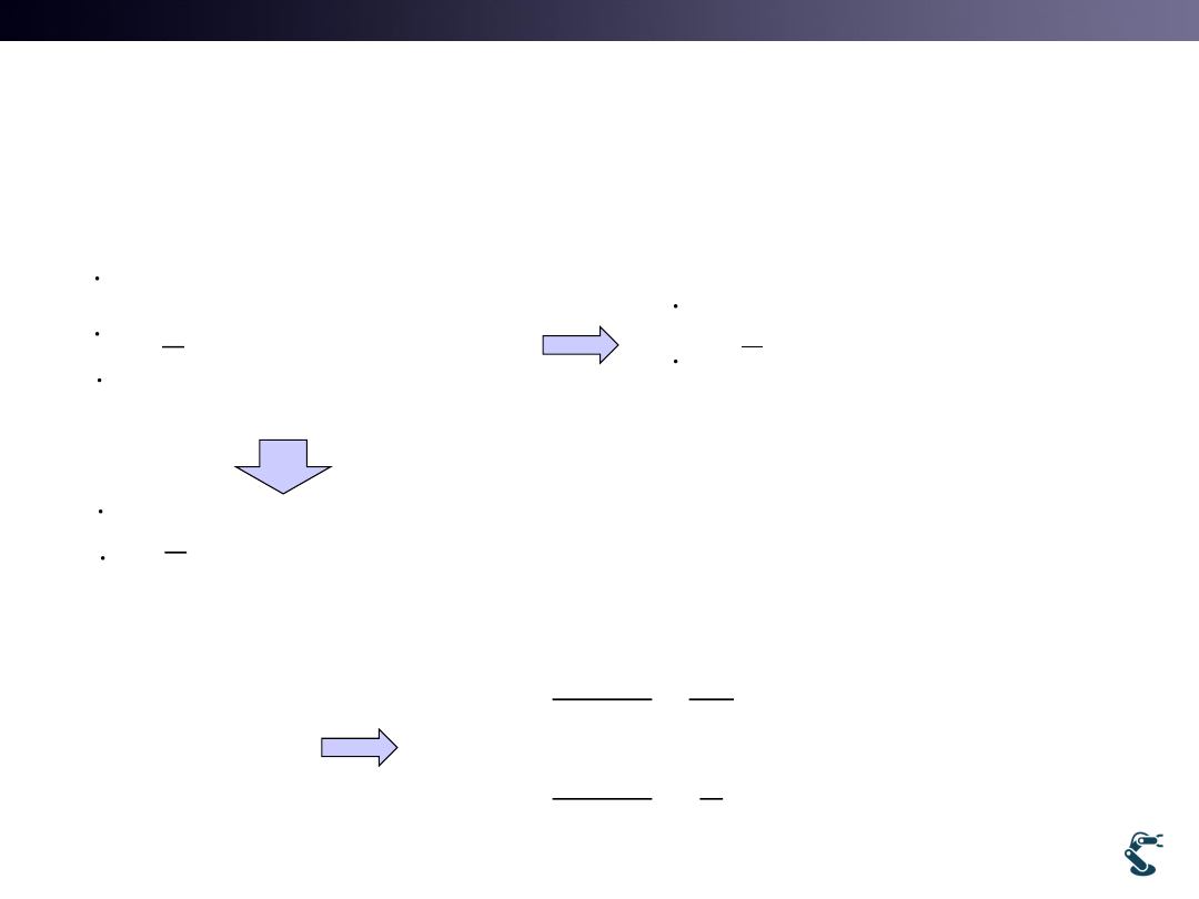
I. Simple Strategy:
Rotation-Translation-Rotation
• 1. Translation by WL=WR=Wo
– A robot cannot reach the desired position.
– It is over constrained..
– Wo cannot satisfy two different values, dx and dy.
• 2. Rotation by WL= (-) WR=Wo
– A robot does not Move but only rotate at an initial position.
– It is also Over constrained so that a robot cannot move to
the desired position.
29
2 cos
r cos
2 sin
r sin
2
0
0
o
o
x
r
y
w
w
cos
cos
0
sin
sin
0
2
1 /
1 /
/
o
o
o
x
w
r
y
w
a
a
rw
a
T&C LAB-AI
Dept. of Intelligent Robot Eng. MU
Robotics
II. New Strategy for Inverse Kinematics
30
cos
cos
sin
sin
2
1 /
1 /
L
R
x
w
r
y
w
a
a
cos
cos
sin
sin
2
L
R
w
x
r
w
y
cos
cos
1 /
1 /
2
L
R
w
x
r
w
a
a
Det (c*s-c*s)=0
Not invertible.
L
R
w
B
w
1
1
cos
1
cos
a
r
r
B
a
r
r
T&C LAB-AI
Dept. of Intelligent Robot Eng. MU
Robotics
31
cos
cos
sin
sin
2
1 /
1 /
L
R
x
w
r
y
w
a
a
1
L
R
w
x
B
w
cos
cos
1 /
1 /
2
L
R
w
x
r
w
a
a
sin (
)
2
L
R
r
y
w
w
1
1
cos
1
cos
a
r
r
B
a
r
r
1
2
cos
sin
1
2
cos
sin
L
R
a
x
w
r
r
r
y
w
a
r
r
r
2
sin
cos
2
sin
cos
L
R
y
x
a
w
r
r
r
y
x
a
w
r
r
r

T&C LAB-AI
Dept. of Intelligent Robot Eng. MU
Robotics
32
1
2
cos
sin
1
2
cos
sin
L
R
a
x
w
r
r
r
y
w
a
r
r
r
( , , )
x y
𝑥𝑑, 𝑦𝑑, 𝜃𝑑
• Why inverse Jacobian matrix cannot reach
the desired goal exactly?
• 1. The solution is the optimal one NOT the exact
one.
• 2. Remind Inverse Jacobian Method for
manipulator. It is NOT Inverse Kinematics
Limitation of
II. New Strategy for Inverse Kinematics
T&C LAB-AI
Dept. of Intelligent Robot Eng. MU
Robotics
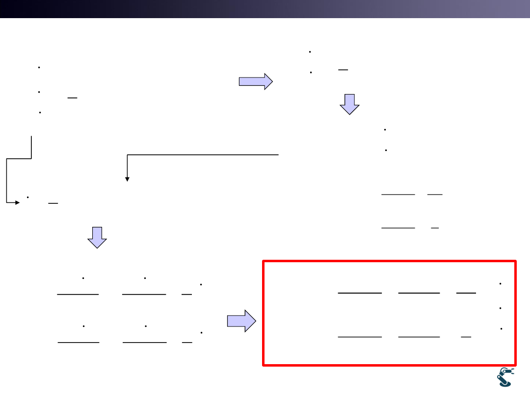
When a Robot Stops?
33
1
2
cos
sin
1
2
cos
sin
L
R
a
x
w
r
r
r
y
w
a
r
r
r
, then
0
d
if
1
2
cos
sin
1
2
cos
sin
L
R
w
x
r
r
w
y
r
r
2
cos
sin
0
L
R
x
y
w
w
r
r
2
2
2
tan
y
y
x
x
Kpe
e
y
x
Kpe
e
•
W/O orientation error, there is
position error.
•
W/O position error, there is
orientation error.
•
Because Jacobian is NOT square
matrix, you CANNOT satisfy all at
once.

T&C LAB-AI
Dept. of Intelligent Robot Eng. MU
Robotics
Inverse Jacobian is used for What?
• Think control
– 1. Need path.
– 2. Control input for only short distance is estimated by
Inverse Jacobian method.
• Now, what is required for a mobile robot?
– we should think about PATH for mobile robot navigation.
Ex) for a valet parking, path is required.
– Also, a mobile robot should KNOW WHERE IT IS?
How to detect the current position (x,y,q)?
34
T&C LAB-AI
Dept. of Intelligent Robot Eng. MU
Robotics
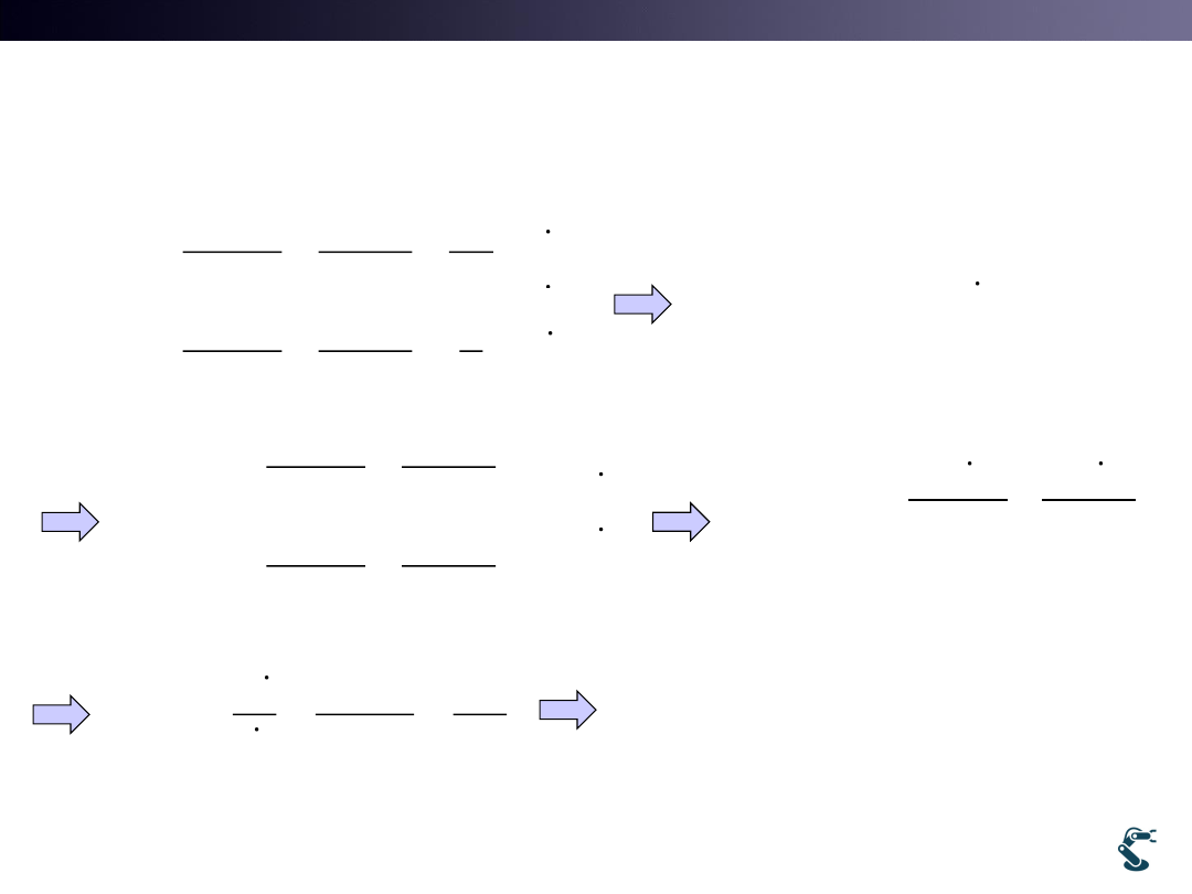
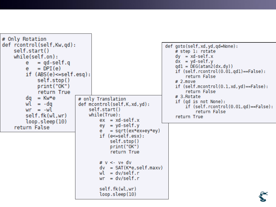
Ex) rover4.py (
con’t)
35
Rotation controller
Translation Controller
Goto with R-T-R
Import kin4
kin4.so.goto(x,y,q)
T&C LAB-AI
Dept. of Intelligent Robot Eng. MU
Robotics
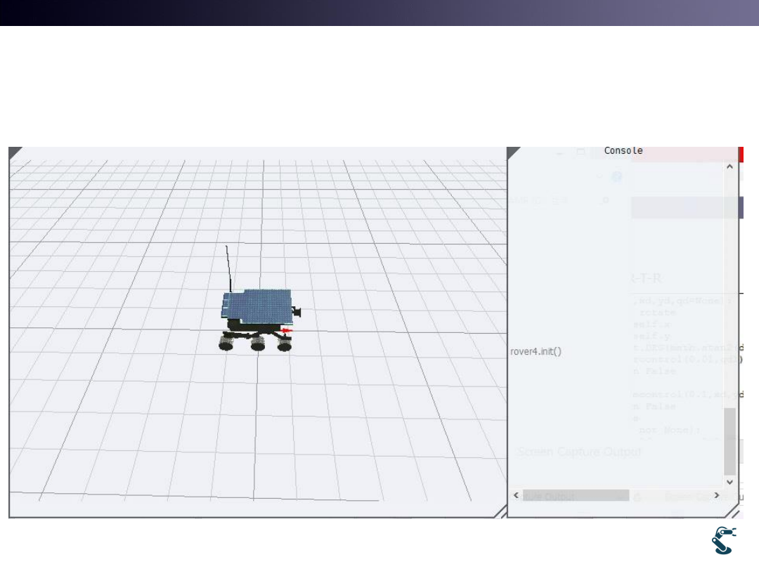
Example) Rover4.py
36
T&C LAB-AI
Dept. of Intelligent Robot Eng. MU
Robotics
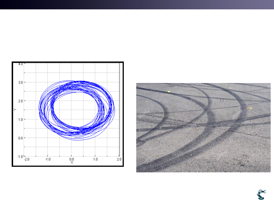
If There are Slips on Wheels,
Forward Kinematics works well?
• If wheel has an error,
then WL or WR has an
error.
37
Skid marks
T&C LAB-AI
Dept. of Intelligent Robot Eng. MU
Robotics
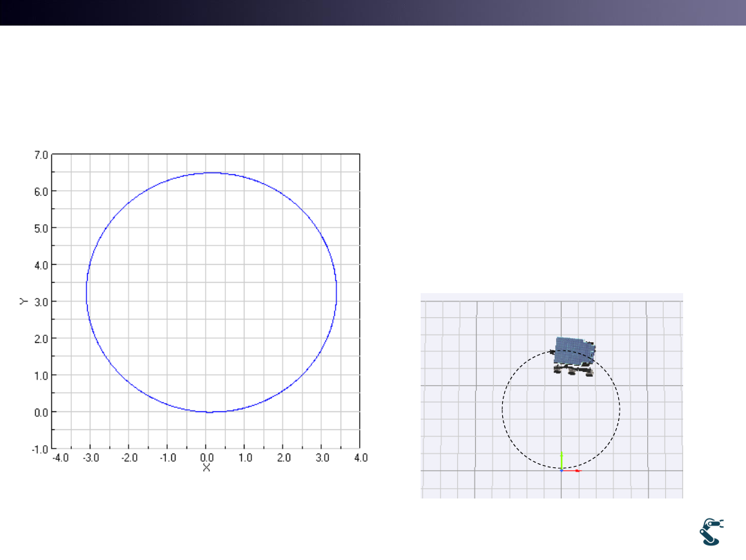
Slip Example: rover3slip1 with No Slip
• rover3slip1.mr.run(3,3.5)
38
T&C LAB-AI
Dept. of Intelligent Robot Eng. MU
Robotics
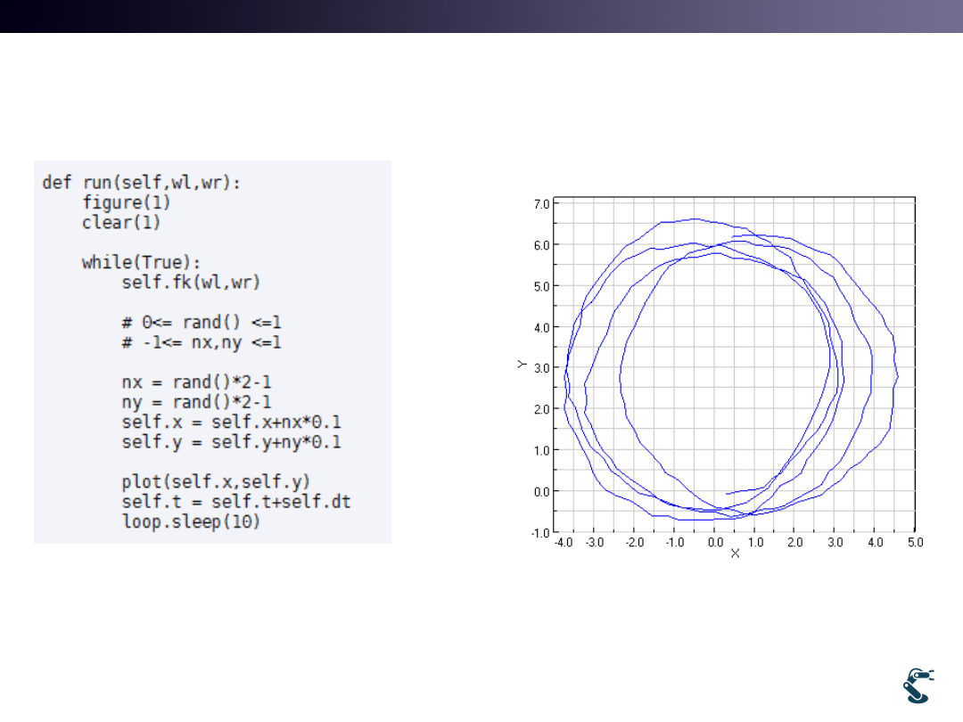
Slip Example: rover3slip2
• [x,y,q] is noisy Localization Error
39
0.1 (0,1) (0,1)
Gaussian Noise
noise
X
X
N
N
T&C LAB-AI
Dept. of Intelligent Robot Eng. MU
Robotics
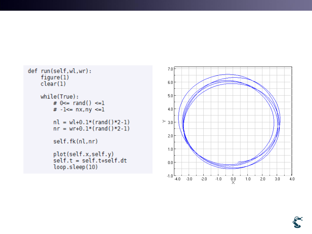
Slip Example: rover3slip3
• [WL, WR] is noisy Wheel slips. Wheel does not roll.
40
w t
(1, 0)
noise
w
w
N

T&C LAB-AI
Dept. of Intelligent Robot Eng. MU
Robotics
41
def move(self,x,y,q): ql, qr =? fk(wl,wr)
self.x
= x;
self.y
= y;
self.q
= q;
h = loop.rspace.H()
h = h.Trans(x,y,0)*h.RotZ(q);
z
= self.r
a
= self.a
self.o.T( h*h.Trans(0,0,z))
self.WL.T(h*h.Trans(0,a,z)*h.RotY(0))
self.WR.T(h*h.Trans(0,-a,z)*h.RotY(0))
HW. ex/robot/cart1 and cart2
ql,qr??

T&C LAB-AI
Dept. of Intelligent Robot Eng. MU
Robotics
HW1. How to calculate ql and qr?
• wl and wr in fk() are the angular velocity.
• From wl and wr, we can calculate ql and qr.
42
HW2. Reduce Position Error
• Mobile Robots have more position error.
– It works with Velocity control, it does not with Position control
• Do mr.goto(6.28,0,0) and go back by mr.goto(0,0,0)
• x,y, q, ql, qr have a lot of error.
• How to reduce those errors?
T&C LAB-AI
Localization
If an error on wheels, how to find
the exact position?
Where is a mobile robot?
2
43

T&C LAB-AI
Dept. of Intelligent Robot Eng. MU
Robotics
Localization
• A robot knows where it is.
• GPS : global positioning system is also localization.
• GPS for a car navigation system? FALSE
– Satellite GPS is the right word.
44
T&C LAB-AI
Dept. of Intelligent Robot Eng. MU
Robotics
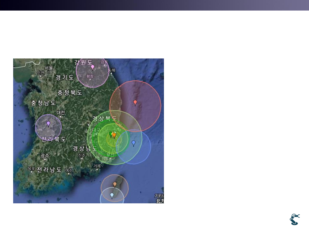
Earthquakes
45
Korea has about 200 sensors.
Japan has about 4000 sensors.
How to localize the earthquake
position?
T&C LAB-AI
Dept. of Intelligent Robot Eng. MU
Robotics
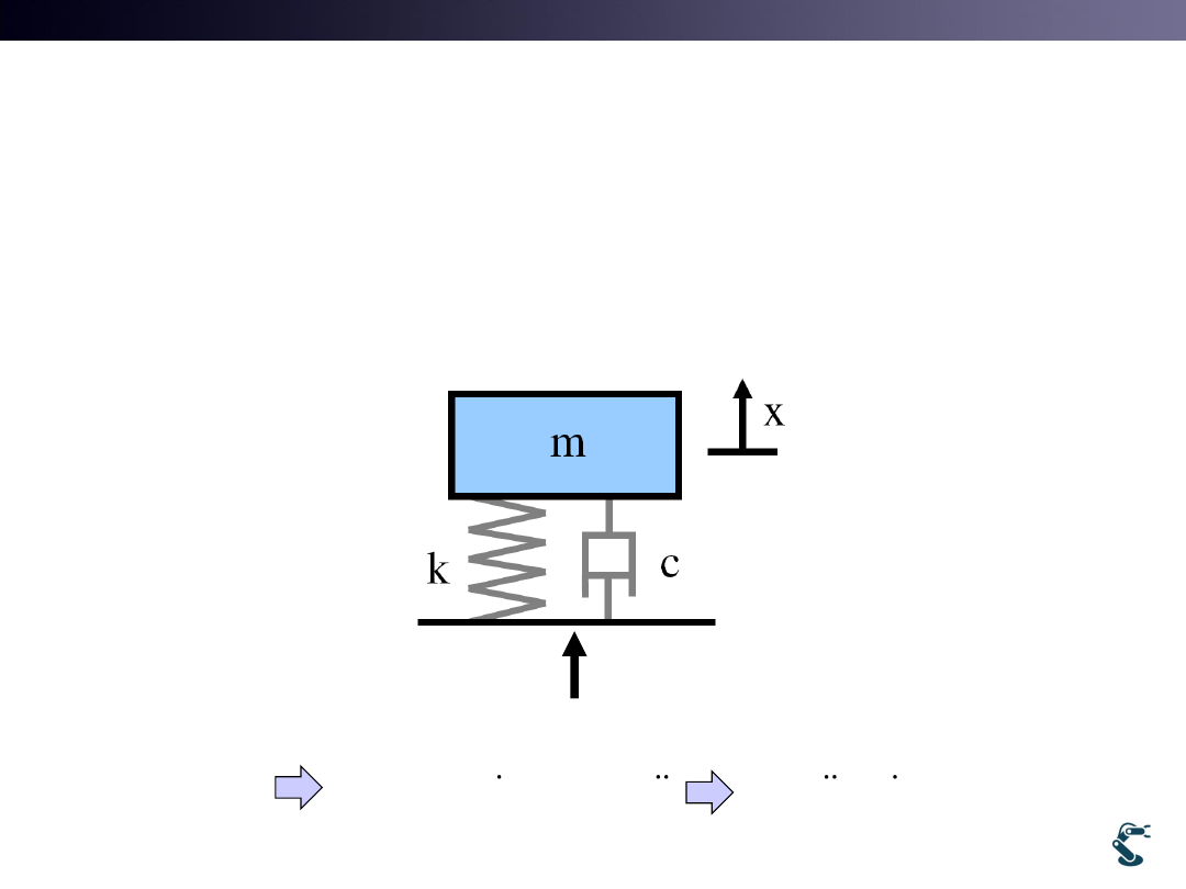
Remind Control Engineering
• Think 1 DOF 2nd order system.
– Mass-Spring-Damper
46
F
ma
F
F
kx cx
ma
mx
mx cx
kx
F
T&C LAB-AI
Dept. of Intelligent Robot Eng. MU
Robotics
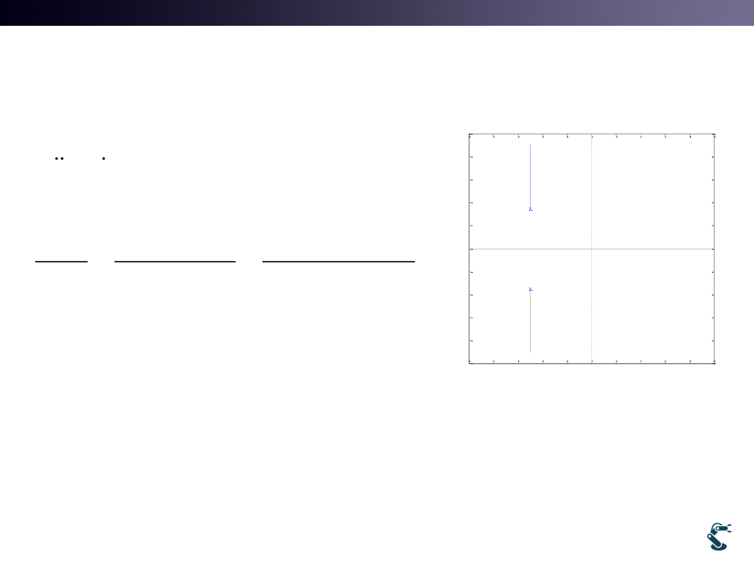
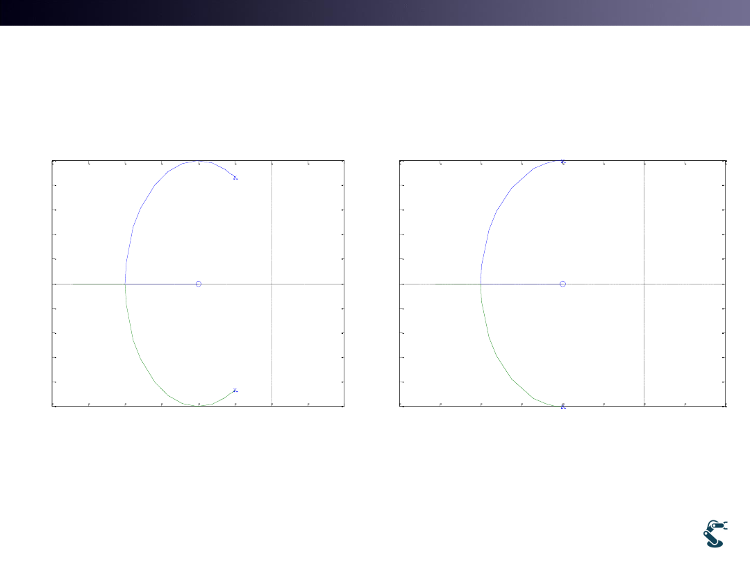
Laplace Transform
• Two poles lie on left half plane.
• It is stable.
• Remind that
Input is Force, F(s) and Output is Displacement, X(s).
47
2
2
1
2
(
) ( )
( )
( )
1
1
( )
(
)(
)
mx
cx
kx
F
ms
cs
k X s
F s
X s
F s
ms
cs
k
s
p
s
p
-1
-0.8
-0.6
-0.4
-0.2
0
0.2
0.4
0.6
0.8
1
-2.5
-2
-1.5
-1
-0.5
0
0.5
1
1.5
2
2.5
Real Axis
Im
a
g
A
x
is
m=c=k=1
rlocus(tf(1, [ 1 1 1]))
T&C LAB-AI
Dept. of Intelligent Robot Eng. MU
Robotics
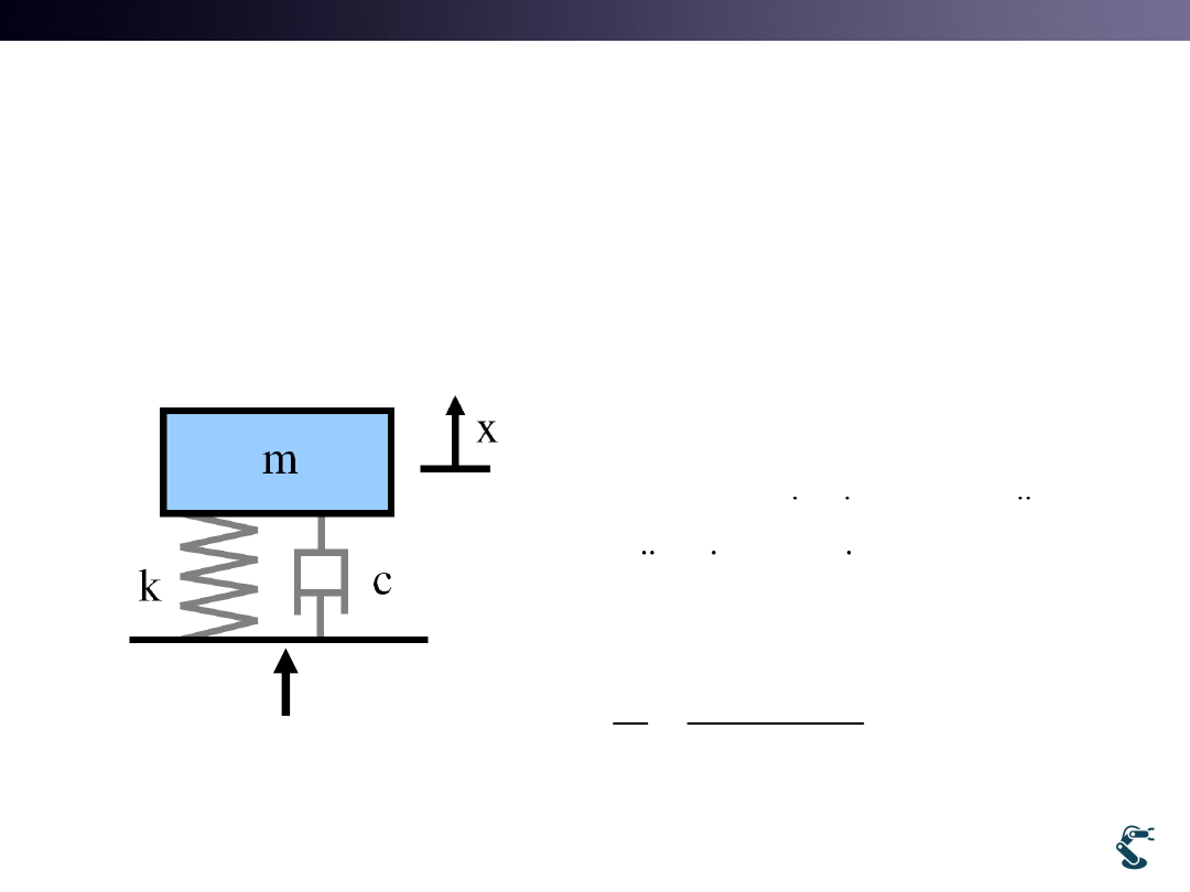
For Earthquake detection,
a New Input becomes displacement.
• Earthquake generate ground vibration
– Ground displacement is the INPUT.
48
Y
F
ma
(
)
(
)
k x
y
c x
y
ma
mx
mx
cx
kx
cy
ky
2
2
(
) X
(
)
ms
cs
k
cs
k Y
X
cs
k
Y
ms
cs
k
What is the different with X/F system? Zero.
T&C LAB-AI
Dept. of Intelligent Robot Eng. MU
Robotics
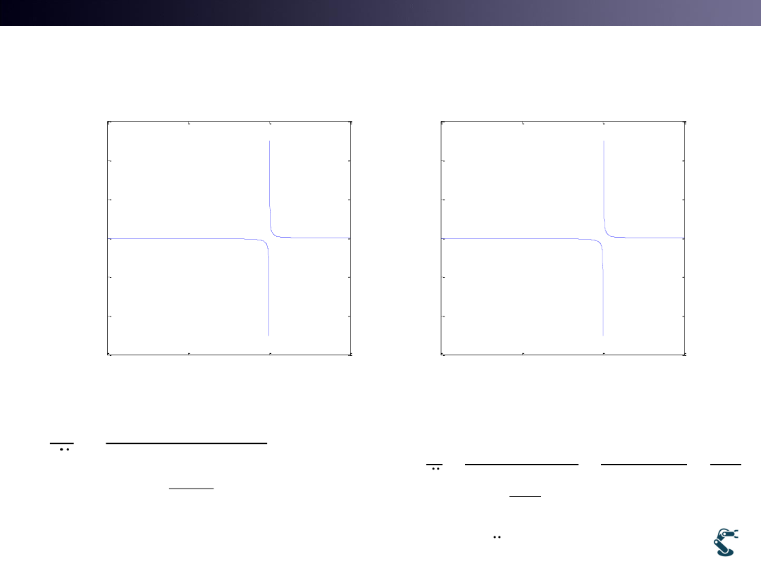
System Behaviors of
Seismic sensor
• Zero shifts root locus to the left half plane.
49
-3
-2.5
-2
-1.5
-1
-0.5
0
0.5
1
-1
-0.8
-0.6
-0.4
-0.2
0
0.2
0.4
0.6
0.8
1
Real Axis
Im
a
g
A
x
is
m=c=k=1
rlocus(tf([1,1], [ 1 1 1]))
-3
-2.5
-2
-1.5
-1
-0.5
0
0.5
1
-1
-0.8
-0.6
-0.4
-0.2
0
0.2
0.4
0.6
0.8
1
Real Axis
Im
a
g
A
x
is
m=0.5
c=k=1

T&C LAB-AI
Dept. of Intelligent Robot Eng. MU
Robotics
Seismic sensor detects Relative motion
between ground input and mass movement
50
Relative motion:
(
)
(
)
z
x
y
k x
y
c x
y
ma
mx
kz
cz
mz
my
my
mz
cz
kz
2
2
For intutive understanding, neglect damping
0
my
mz
kz
Z
ms
Y
ms
k
Instead of Root locus in s plane, we verify frequency domain by s= wj. Remind Bode plot
2
2
2
2
2
2
2
2
2
2
2
2
/
1
1
/
n
n
Z
ms
s
s
Y
ms
k
s
k m
s
w
Z
Z
m
s Y
Y
ms
k
s
k m
s
w
2
2
2
2
2
1
1
1
n
n
n
if s
wj
Z
Y
w
w
w
w
w
2
n
k
w
m
Natural frequency
T&C LAB-AI
Dept. of Intelligent Robot Eng. MU
Robotics
Relative Motion/ Ground Acceleration
51
2
2
2
1
1
n
n
Z
Y
w
w
w
0
0.5
1
1.5
-6
-4
-2
0
2
4
6
x 10
-4
Z/
Y
a
w/wn
0
500
1000
1500
-6
-4
-2
0
2
4
6
x 10
-4
Z/
Y
a
w
Testseismic.m
w = 0~ 1500
Wn = 1000
2
2
2
2
2
w<<w
1
1
1
0 1
1
n
n
n
n
n
if
Z
Y
w
w
w
w
w
Z
kY

T&C LAB-AI
Dept. of Intelligent Robot Eng. MU
Robotics
Seismic Sensor
• We cannot measure ground vibration directly.
the displacement of a mass can be measured.
• Seismic sensor attempts to increase Wn to avoid
resonance area.
• If w<<wn , the relative motion z is proportional to
ground acceleration.
• Question: Can you directly measure acceleration of
moving object?
NO. IMU sensor has the same background..
52
T&C LAB-AI
Dept. of Intelligent Robot Eng. MU
Robotics
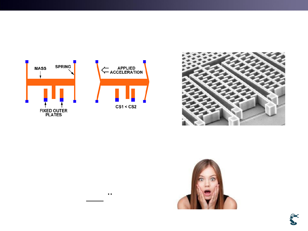
Accelerometer with MEMS
• Under the condition, w<<wn , measured capacitance
detects relative motion, which is proportional to the
acceleration.
53
2
w<<w
1
n
n
if
Z
Y
w
The world can be analyzed in most cases.
T&C LAB-AI
Dept. of Intelligent Robot Eng. MU
Robotics
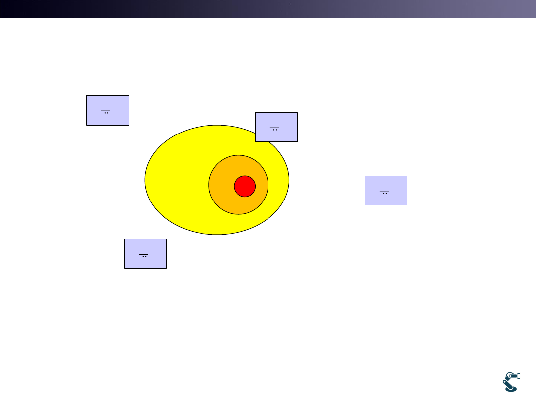
Why Earthquake for Localization
• At given time, all Zi are under consideration.
• Can we estimate the earthquake position?
• |Xearthquake-Xi| = a*Zi
54
Z
Y
Z
Y
Z
Y
Z
Y
Z1
Z2
Z3
Z4
X1
X2
X3
X4
T&C LAB-AI
Dept. of Intelligent Robot Eng. MU
Robotics
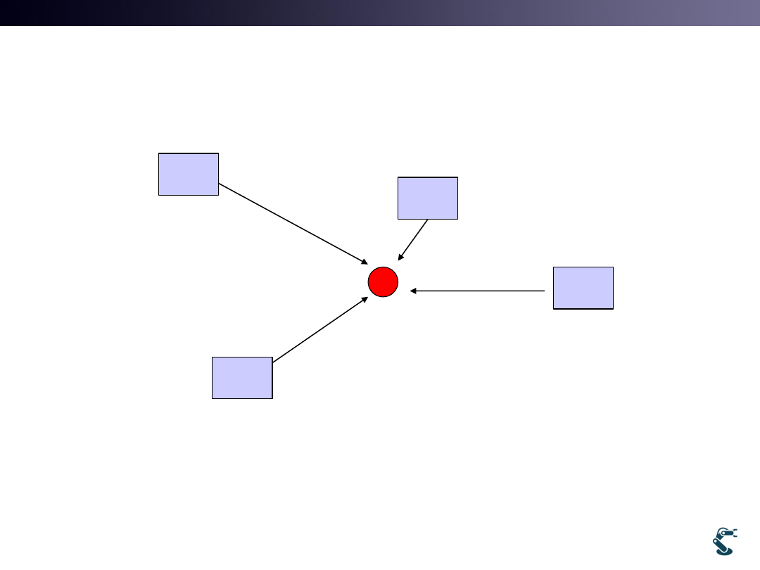
In the same manner,
Beacon-based Localization.
• Solve equations,
Zi = |Xi-X| X
55
Z
Z
Z
Z
X
Z1
Z2
Z3
Z4
X1
X2
X3
X4

T&C LAB-AI
Dept. of Intelligent Robot Eng. MU
Robotics
How to Solve equations?
Cost Optimization
• Current position: (x,y) unknowns.
• Beacon position
– (0,0) , (10,0) , (0,10)
• Three distance equations.
– |x-0|+|y-0|= d1
– |x-10|+|y-0|=d2
– |x-0|+|y-10|=d3
• Absolute value is inconvenient for differentiation
• So, two norm is used.
56
2
2
2
1
2
2
2
2
2
2
2
3
||
0 ||
||
0 ||
||
10 ||
||
0 ||
||
0 ||
||
10 ||
x
y
d
x
y
d
x
y
d
Find x,y

T&C LAB-AI
Dept. of Intelligent Robot Eng. MU
Robotics
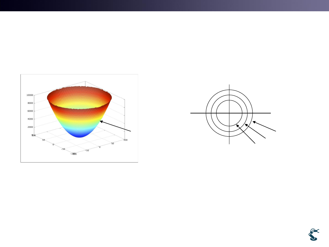
Optimization
Convex hull should be exist
• Convex hull means that it is one of the local minima.
• Think that Y=x^2 has the minimum value at x=0
• In 2D problem. A = x^2 +y^2 has the minimum at x=0
and y=0
57
Local minimum
Local minimum

T&C LAB-AI
Dept. of Intelligent Robot Eng. MU
Robotics
Gradient Descent Method.
• Gradient of function
– Is defined
– Keep in mind that gradient is a VECTOR.
• When f(x,y) = x^2+y^2
58
( , )
(
,
)
f
f
f x y
x
y
ˆ
ˆ
( , )
(2 )
(2 )
f x y
x i
y j
f=3
f=2
f=1
ˆ
ˆ
(0, 0)
0
0
f
i
j
ˆ
ˆ
(1, 0)
2
0
ˆ
ˆ
(1,1)
2
2
ˆ
ˆ
( 1, 0)
2
0
ˆ
ˆ
(0, 1)
0
2
f
i
j
f
i
j
f
i
j
f
i
j
Gradient
is
a normal
Vector!
T&C LAB-AI
Dept. of Intelligent Robot Eng. MU
Robotics
Gradient Descent follows
• Gradient Descent stops at minimum.
59
( )
( , )
f x y
f(x,y) = x^2+y^2
( )
( , )
f x y
Repeat
-
( )
if
then stops.
old
X
guess
X
X
f X
X
X
T&C LAB-AI
Dept. of Intelligent Robot Eng. MU
Robotics
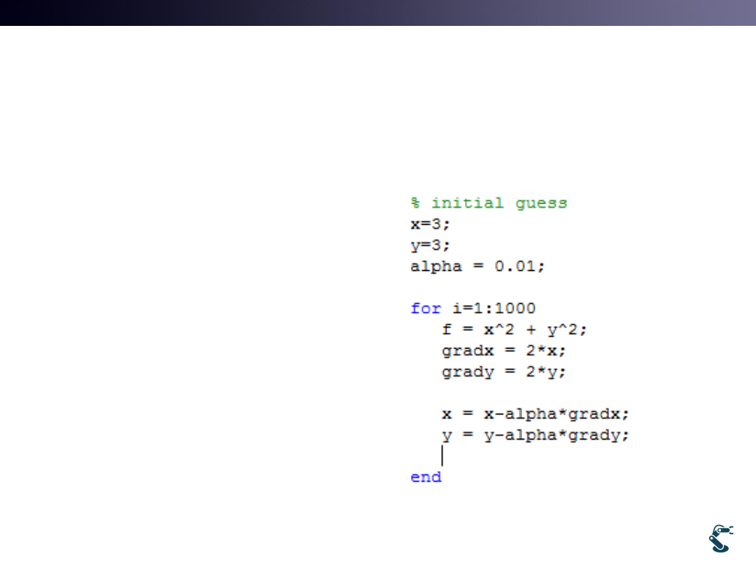
Gradient Descent Example
• Testgd.m
60
2
2
2
2
f
x
y
f
xi
yj
We know that x=0 and y=0 is the
minimum.
Initial guess, x=3, y=3
Alpha = 0.01
x x-alpha*2x
y y-alpha*2y
X 3 – 0.01*2*3 = 2.94
X 2.94 -0.01*2*2.94 = 2.88
X 2.88 -0.01*2*2.88 = 2.85
….
X 0

T&C LAB-AI
Dept. of Intelligent Robot Eng. MU
Robotics
Beacon-based Localization
Iterative Optimal Problem.
• Cost function, f
61
2
:
: the ith beacon position
: estimated distance from X to B
|| X B ||
i
i
i
i
X unknown position
B
d
2
2
2
2
2
,
,
||
||
ˆ
ˆ
4 ||
||
((
)
(
) )
N
i
i
i
N
i
i
x i
y i
i
f
X
B
d
f
X
B
d
x
B
i
y
B
j
2
2
ˆ
4
||
||
(X
) u
N
T
i
i
i
i
X
X
X
B
d
B
T&C LAB-AI
Dept. of Intelligent Robot Eng. MU
Robotics
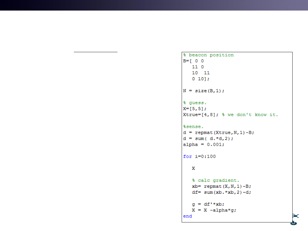
Example of Beacon-based Localization
• Testb.m
• Beacon position = B
• B = [ bx1, by1
•
…..
•
bx4, by4]
• 1.d = (xtrue –B)^2
• 2.xb = X-B
• 3.df = xb^2 –d
• Gradient = df *xb
62
2
2
ˆ
4
||
||
(X
) u
N
T
i
i
i
i
X
X
X
B
d
B
1
2
3

T&C LAB-AI
Dept. of Intelligent Robot Eng. MU
Robotics
Gradient Descent Method, GDM
• You should learn GDM.
• Neural network is one of the example based on GDM.
• Over 80% of engineering method uses GDM.
• However, before use GDM, you should think about the
convex hull problem.
• If there is no convex hull, GDM will be diverged.
63

T&C LAB-AI
Dept. of Intelligent Robot Eng. MU
Robotics
However, calculation d has Noise.
• Uncertainty
– Beacon position has errors.
– Distance sensing has errors.
• Testb2: 4 beacons with errors.
– Add Gaussian noise. B = B+ N(0,s) d = d+N(0,s)
– Result : position estimation error = (0.29, -0.115) |e|=0.31
• Testb3: 5 beacons with errors.
–
position estimation error = (0.0086, -0.2003) |e|=0.20
• The more beacons, the better accuracy.
– Remind that it is optimal problem cost function f cannot be
zero.
64
